


Typical structure of injection moulds
The parts of an injection mold are divided into the following categories based on their different functions.
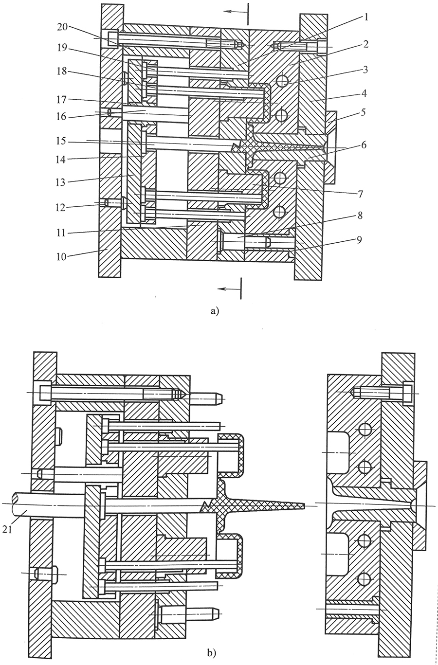
a) Mold closing state b) Mold opening state
1-Moving half of a mold; 2-Fixed half of a mold; 3-Cooling channel; 4-Clamping plate of the fixed half; 5-Locating ring; 6-Sprue bush; 7- Punch; 8-Guide pillar; 9-Guide bush; 10-Clamping plate of the moving half; 11-Support plate; 12-Limit pin; 13-Ejector plate; 14-Ejector retainer plate; 15-Sprue puller pin; 16-Ejector guide pillar; 17-Ejector guide bush; 18-Ejector pin; 19-Return pin; 20-Spacer; 21-Lifting pin of injection maching
1 Forming Part
The forming part consist of the punch (as known as the core), the cavity plate (also know as the cavity). When the whole mold is closed, a cavity is established. In the mold illustrated in below figure, the cavity is produced by fixed half of a mould (2) and punch (7).
2 Feed System
The feed system refers to the passage-way through which the molten plastic passes from the nozzle of the injection machine into mold cavity. It consists of four parts: sprue, runner, gate and cold slug well.
3 Guide Mechanism
In order to guarantee correct mold assembly between movable mold and stationary mold, it is necessary that guide pillar and guide bush is used in moving half of a mold and fixed half of a mold (8,9) or anastomotic cone cooperated inside and outside is set in moving.
4 Side parting and core-pulling mechanism
If the plastic part has a side concave or a side bulge, the movable core forming the concave or the bulge must be taken out from the plastic part before the mold can be smoothly opened and the plastic part knocked out. The device to realize this function is the side parting and core-pulling mechanism. In the mold shown in figure(3~13) , the side parting and core-pulling mechanism consists of the angle pin 2, angled siding split (side core) 3, the stop pin 4, and the wedge block 1.
5 Ejecting Mechanism
The ejecting mechanism means the equipment push-off plastic part from mold after parting. In the mold as figure(3~17) show, the ejecting mechanism consists together of ejector plate (13) and ejector retainer plate (14), and sprue puller pin (15), and ejector guide pillar (16), and ejector guide bush (17), and ejector pin (18), and return pin (19).
6 Temperature adjustable system
In order to meet the demand on temperature of the mold in the injection technology, the temperature of the mold must be controlled, so a temperature adjustment system is normally installed for cooling or heating the mold. The cooling system is generally realized through the wooling channel on the mold, as is shown by the wooling channel (3). The heating system consists of the heating elements inside or around the mold.
7 Exhaust and overflowing system
In order to exhaust gases inside the cavity in the process of injection and forming, an exhaust and overflowing system must be set up. Gases can be exhausted by the parting line, by air vent purposefully made on the parting line, or through the fit clearance between the ejector pin or core and the mold plate.
8 Parts for supporting
The supporting parts refer to those parts that are used to install, fasten and support forming elements. These parts assembled together form the mold-set of the injection mold. In the mold shown in figure (3~17), the supporting parts consist of moving half (10), support plate (11), and spacer (20).
Case Studies

- Tooling
- Injection Molding
- injection moulds
Related Tags :


