


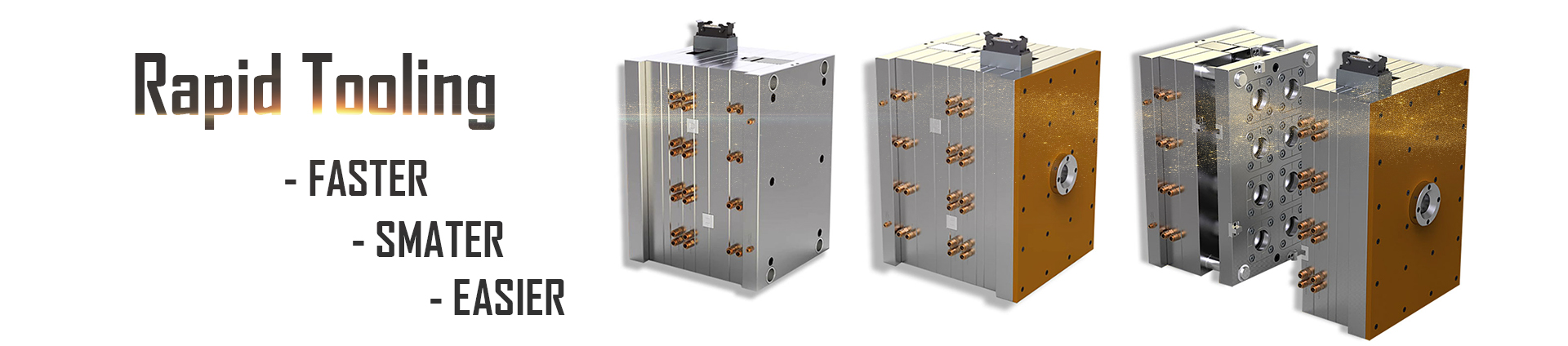
Design for Manufacture
A very important aspect of project planning is assessing the design for manufacturability.
During this phase, E-Mold project managers and engineers are looking for anything that might cause problems in the molding process including both cosmetic and dimensional issues. Typical issues include wall thickness, wall to rib ratio, draft angles, undercuts, weld line locations, and texture choices.
It is important that both E-Mold and customer are working to the agreed DFM. This avoids confusion, delays, expensive mistakes and disagreements later.
Without a clearly confirmed DFM, the mold design would not be started.
Below is the list of the items covered in DFM:
1. Overview of Part information
4. Slider Actuation required
8. Metal insert overmold
9. Sharp or thin steel
Component tolerances
All dimensions and tolerances in 2D drawing must be present and the material clearly specified.
E-Mold will check and make sure that the tolerances required can be met in production,
if any queries, E-Mold may have should be taken up and discussed and agreed with customer and a new drawing issued.
Parting line & Orientation
https://www.e-moldrapid.com/choice-of-plastic-tooling-parting-line-a-33.html
Surface textures and finishes
The Average Surface roughness (Ra) is specified in microns (Ra=Arithmetic mean)
The level of surface roughness should be confirmed by customer, sometimes it is better to use a reference sample.
| SPI-Surface Finish | Method of achieving surface finish | µm(Min>Max) | µ inch(Min>Max) | Description |
| A1 (optical quality finish) | 3 micron diamond paste | 0 > 0.025 | 0 > 1 | For mirror or optical finishes. Most time consuming. Steel grade important to results. |
| A2 (mirror finish) | 6 micron diamond paste | 0.025 > 0.05 | 1 > 2 | |
| A3 (High polish) | 15 micron diamond paste | 0.05 > 0.075 | 2 > 3 | |
| B1 | 600 grit fine paper | 0.05 > 0.075 | 2 > 3 | Removes all tool machining marks. Provides good mold release. Light reflecting finish on molded part, some sheen. |
| B2 | 400 grit fine paper | 0.1 > 0.125 | 4 > 5 | |
| B3 | 320 grit fine paper | 0.225 > 0.25 | 9 > 10 | |
| C1 | 600 grinding wheel of stone | 0.25 > 0.3 | 10 > 12 | Removes all tool and machining marks. Provides good mold release. Mute finish on molded part, no sheen. |
| C2 | 400 grinding wheel of stone | 0.625 > 0.7 | 25 > 28 | |
| C3 | 320 grinding wheel of stone | 0.95 > 1.05 | 38 > 42 | |
| D1 (Satin finish) | #11 glass bead dry blast | 0.25 > 0.3 | 10 > 12 | For decorative finishes. Often used for die cast and thermoset cooling. Helps hide shrink marks and other imperfections. Dull, non reflecting finish on molded or cast part. |
| D2 (Dull finish) | 240 A1203 grit dry blast | 0.65 > 0.8 | 26 > 32 | |
| D3 (Dull finish) | #24 A1203 dry blast | 4.75 > 5.75 | 190 > 230 |
Draft analysis
A draft angle of at least 1° is required for most Tooling, but for deep drawn components with long sides 2° or more is preferable.
If draft angles are not present on the drawing, E-Mold will pursue this problem
with customer with a view to obtaining a concession.
Precision moldings with close tolerances often mean that draft angles cannot be used, as they may take the part out of tolerance. In such cases, it may be possible to provide a small amount of draft by using the maximum and minimum tolerance conditions of the dimensions. If this method is employed, however, sufficient tolerance should remain to allow for variations in sizes from part to part during molding.
Ejecting
Ejecting should be considered to avoid ejecting on appearance faces.
The most common forms of ejection are as follows:
- Pins and blades
- Sleeve ejectors
- Stripping actions
- Valve ejectors
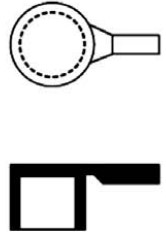
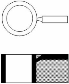
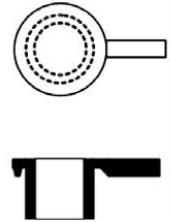
Runner & Gate
The gate location should be selected in such a way that rapid and uniform mold filling is ensured and the weld/meld lines (if any) and air vents are positioned properly. The gate should be positioned away from load-bearing areas. This is because the high melt
pressure and high velocity of flowing material at a gate causes the area near a gate to be highly stressed.
We need customer confirm the gate location if on the important surface, or if it would affect the final assemble.
Below table shows the most common types of gates. Gates may have a variety of configurations.
|
Direct or Sprue Gate Usually used for single cavity molds where the sprue feeds the material directly in the cavity rapidly and with mininum pressure drop. The disadvantage of this system is that the gate has to be trimmed off and a large gate witness is left on the part. The sprue diameter at the point of entry to the cavity should be approx twice the thickness of the molding at that point. Gate diameters range from 1.5 to 6.5mm and 1.6 to 12.5mm in length with a minimun taper of 1° per side. |
 |
|
Tab Gate Typically used for flat, thin parts to reduce the shear stress in the cavity. The high shear stress is confined to the tab which is trimmed off after molding. Tab gates are used frequently for molding PVC, Acrylic(PMMA), ABS material. The minimun effective tab width is 6.4mm and the minimun thickness is 75% of the cavity depth. |
 |
|
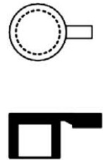
Edge or Side gate Located at the parting line of the mold and fills the cavity from side, top of bottom of the part. Typical gate size is 0.4 to 6.4mm, thick and 1.6 to 12.5mm wide. |
 |
|
Fan Gate A gate similar to a wide edge gate with a variable thickness. It permits rapid filling of large parts or fragile mold sections through the large entry area. It is used to create a uniform flow front into wide parts where warpage and dimensional are the main concerns. Typical gate sizes range from 0.25 to 1.6mm thick and the width 6.4 mm to 25% of the cavity length. |
 |
|
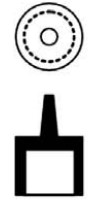
Disc or Diaphragm Gates Frequently used for gating cylindrical or round parts that have an open inside diameter. Used when concentricity requirements are important and weld line unacceptable. Typical gate thickness is 0.25 to 1.27mm. |
 |
|
Pin Gate A pin gate is generally used in three plate and hot runner tools to permit rapid gate freeze off and easy de-gating. The runner is automatically trimmed from the molding with a stripper plate as the mold opens. Gate sizes typically range from 0.25 to 1.6mm diameter. |
 |
|
Submarine or Tunnel Gate A sub gate is mainly used in two plate molds. They consist of a tapered, angle hole machined from the main runner to the cavity below the split linne. It enables automatic de-gating of the part from the runner during the ejection phase. Typical gate sizes are 0.25 to 2mm in diameter at the point of entry in the cavity. |
 |
|
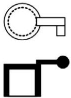
Ring Gate A ring gate is sometimes used for gating round or cylindrical parts. The material flows freely around the core before it flows down as a uniform front to fill the cavity. Typical gate thickness is 0.25 to 1.6mm |
 |
|
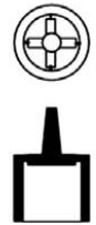
Spoke or Spider Gate This is also called a four point or cross gate. It is used for tubular parts and offers much easier de-gating than the ring gate. Disadvantages include the possibility of weld lines and out of roundness. Typical gate sizes range from 0.8 to 4.8mm thick and 1.6 to 6.4 wide. |
 |
|
Film or Flash Gate This is similar to a ring gate but is used for flat, straight parts. It consists of a straight runner and a gate land across eigher the entire length or width of the cavity or a portion of it. It is often used for Acrylic parts and large flat areas to keep warpage to a minimun. Gates are typically 0.25 to 0.63mm |
 |
|
Hot Probe Gate A hot probe gate or a hot runner gate is normally used to deliver material directly into the cavity through heated runners resulting in runnerless moldings. |
 |
Wall thickness
One of the main issues faced during project design is wall thickness.
The wall thickness depends on many factors and there is no density that works universally for all projects, so it must be customized per part.
Wall thickness is important because it affects processing of the part and depending on how far the material needs to flow, this can affect both cosmetics and dimensions.
If the walls are too thin than the melted plastic moves slowly through the tool, which makes it difficult to fill.
On the other hand, if the walls are too thick than it takes longer for the plastic to cool, which can cause part shrinkage. This happens because the areas of plastic on the outside cool more quickly than the inside, which can cave in.
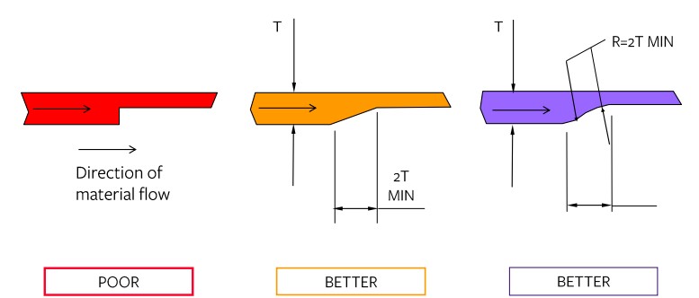
Where possible, there needs to be even wall thickness and smooth transitions for the material to flow through correctly.
Importance of maintaining an even wall thickness to achieve best part quality.
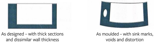
Where changes in wall thickness are essential it is important to ensure even flow is achieved by smoothing the transition:
Wall thickness to material type:
| Typical Wall Thickness (mm) | Polymer (Abbreviation) |
| 0.6 to 4.0mm | Acrylic (PMMA) |
| 0.5 to 4.0mm | Polypropylene (PP) |
| 0.7 to 5.5mm | Acetal (POM) |
| 0.5 to 4.5mm | Polystyrene (HIPS) |
| 1.0 to 6.0mm | Polycarbonate (PC) |
| 1.0 to 4.5mm | Acrylontrile Butadiene Styrene (ABS) |
| 0.7 to 4.5mm | PC/ABS blend |
| 0.5 to 5.5mm | Polyamide (Nylon 6/66) |
Wall to rib ratios are another important consideration during part design. Ribs are commonly used in plastics manufacturing as a way to increase the strength of the part structurally. It's important to note that rib thickness must be 60% or less than the wall thickness of the part or the ribs will sink and be seen through the other side of the part.
One of the main considerations during injection molding manufacturing is the part draft angles. This is because the part needs to be able to get out of the tool and to do this there cannot be a 0 degree, or exactly perpendicular, draft. A 0 degree draft angle would cause the part to get stuck inside the tool. A part with heavy texture will need to increase the draft angles even more because the plastic is more likely to stick to the tool. The key takeaway here is that correct draft angles will make the part look good without getting stuck.
During the stage of project planning when part design occurs, all of these factors are critical to build a successful part that meets customer specifications. The main issues to consider in regards to part design include wall thickness, wall to rib ratio, draft angles, undercuts, weld lines, and texture.


