




How Sheet Metal Fabrication Works for Custom OEM Parts Production
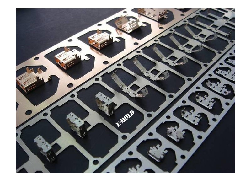 Sheet metal fabrication begins with flat metal stock and transforms it into functional parts through a sequence of design review, cutting, bending, forming, finishing and inspection steps. The final process depends on the material, sheet thickness, part geometry, required tolerances, production volume and intended application.
This guide explains how sheet metal parts move from drawings and CAD files to finished components. It is intended for engineers, procurement teams and product development professionals who need to understand the sheet metal fabrication process before selecting a manufacturing method or preparing a custom part for production.
For buyers looking for a supplier to review and manufacture custom parts, see E-mold’s Sheet Metal Fabrication services.
Design Review and Flat Pattern Development
The manufacturing process usually begins with a review of the part design. At this stage, the manufacturing team examines the 2D drawing, 3D CAD model, material requirements, sheet thickness, bend locations, holes, cutouts, formed features and assembly relationships.
A 3D CAD model helps communicate the overall shape and spatial relationship of the part. A 2D drawing is often needed to define dimensions, tolerances, datums, surface requirements and inspection expectations. When the two files are inconsistent or important information is missing, the supplier may need clarification before production can begin.
Flat Pattern Development
A formed sheet metal part usually starts as a flat blank. The flat pattern represents the shape that must be cut before the part is bent or formed. Developing this pattern requires consideration of material thickness, bend radius, bend allowance and the amount of material consumed by each bend.
The developed flat pattern is not always a simple projection of the finished part. Bending changes the geometry of the material, and the neutral axis or bend allowance must be considered when calculating the required flat dimensions. An incorrect flat pattern can result in dimensional errors after forming, even if the original 3D model appears correct.
Bend Allowance and Bend Sequence
Bend allowance describes the amount of material required in the bend region. The appropriate value depends on factors such as material behavior, sheet thickness, bend radius and forming method. The bend sequence also matters because one bend may restrict access to another feature or change the way the part is positioned during a later operation.
Holes, slots and cutouts should be reviewed in relation to nearby bends. A feature placed too close to a bend may distort during forming or become difficult to hold within the required tolerance. Assembly features, mounting points and mating surfaces should also be identified during design review.
Cutting and Feature Formation
After the flat pattern is defined, the sheet is cut to create the outer profile and internal features. Depending on the material, thickness, geometry and production requirements, sheet metal parts may be cut using laser cutting, waterjet cutting, plasma cutting, punching or shearing methods.
These are common industry methods, and the suitable option depends on the part design and manufacturing plan. A method that works well for a thin prototype may not be the most appropriate choice for a thick structural component or a high-volume production part.
Laser Cutting
Laser cutting uses a concentrated beam to separate material along a programmed profile. It can be suitable for complex external contours, holes and cutouts, particularly when the design requires flexible programming and does not justify dedicated hard tooling.
The quality of a laser-cut edge can be influenced by material type, thickness, machine settings, heat input and the condition of the cutting equipment. Buyers should identify whether the edge condition is functionally important or whether a later deburring or finishing step is acceptable.
Waterjet and Plasma Cutting
Waterjet cutting uses a high-pressure abrasive stream to separate material without relying on the same heat input as thermal cutting methods. Plasma cutting uses a high-temperature plasma arc and is often associated with conductive metals and larger profiles. Both methods have different operating ranges, edge characteristics and production considerations.
These methods should be selected based on the material, thickness, profile, required edge quality, tolerance and production volume. They should not be assumed to be interchangeable for every sheet metal component.
Punching, Shearing and Blanking
Punching uses a punch and die to create holes, slots or other features. Shearing separates sheet material along a cutting line, while blanking removes a defined part profile from the sheet. In some production arrangements, punching and blanking may be combined with forming operations or progressive tooling.
Punch and die alignment, clearance and tool condition can affect the edge quality and dimensional accuracy of the feature. The design should also consider the relationship between hole size, sheet thickness, hole spacing and the distance from the edge of the material.
Bending and Forming
Bending changes a flat sheet into an angled or contoured structure. Press brake bending is commonly used for straight bends, while roll forming gradually bends a sheet or strip through a sequence of forming rolls. Stamping and other forming methods use dies to create repeated shapes or formed features.
The final result depends on material properties, sheet thickness, bend radius, tool geometry, forming force and the number and order of operations.
Press Brake Bending
A press brake forms sheet metal by pressing it between an upper tool and a lower die. Different tool geometries can create different bend angles, channels, flanges and profiles. The same part may require several operations if it contains multiple bends or features that cannot be formed in one setup.
Part positioning and bend sequence are important. A completed bend may prevent the part from being placed correctly for a later operation. Engineers and suppliers may therefore review the order of operations before production to reduce interference and improve repeatability.
Bend Radius and Springback
The bend radius is the radius formed at the inside or outside of a bend. A radius that is too small for the material and sheet thickness may increase the risk of cracking or deformation. A larger radius may reduce the risk of cracking but can affect the overall geometry and available space within the assembly.
Springback is the tendency of the material to partially return toward its original shape after the forming force is removed. Material strength, thickness, bend radius and forming method can influence the amount of springback. The effect should be considered when defining bend angles and critical dimensions.
Roll Forming
Roll forming feeds sheet or strip through a series of paired rollers. Each roller station creates a gradual bend until the material reaches the required profile. This process is suitable for continuous production of long parts with consistent cross-sections and parallel bends.
Roll forming typically requires dedicated tooling and careful control of the material, roller sequence and profile geometry. It may be more suitable for repeat production of long or continuous profiles than for an isolated prototype with frequently changing geometry.
Deep Drawing, Spinning and Specialized Forming
Some sheet metal parts require forming beyond simple straight bends. Deep drawing uses a punch and die to draw a flat blank into a cup, box or other deeper three-dimensional shape. The process must account for material flow, wall thinning, wrinkling and the required forming depth.
Spinning forms a circular sheet metal blank over a rotating mandrel or form. It can be used for rotationally symmetrical parts such as covers, cones or other circular components. The suitability of spinning depends on the part geometry, material, quantity and required dimensional consistency.
Stamping can include operations such as blanking, piercing, bending, drawing, embossing and forming. Depending on the part and production volume, stamping may use dedicated dies or other tooling arrangements. Specialized forming processes should be evaluated according to the design and quantity rather than selected only because they appear faster in theory.
Roll forming, deep drawing and spinning are described here as common industry processes. Their availability for a specific project depends on the selected supplier, equipment, tooling arrangement, part geometry and production plan.
Surface Finishing
Surface finishing is applied after fabrication or at a defined stage within the production sequence. The purpose may be to improve appearance, protect the material, support identification, improve wear resistance or meet a specific assembly requirement.
Common sheet metal finishing methods include painting, plating, anodizing, powder coating, printing, laser marking and hot stamping. The appropriate option depends on the base material, environmental exposure, appearance requirement, functional purpose and production conditions.
Painting and Powder Coating
Painting can provide color, appearance and a degree of surface protection. Powder coating applies a dry coating material that is then cured to form a finished surface. These methods require the buyer to define color, gloss, texture, coverage and areas that should remain uncoated.
Plating and Anodizing
Plating deposits a metal layer or coating onto the surface to achieve a desired appearance or functional property. Anodizing is an electrochemical treatment commonly associated with aluminum and can alter the surface appearance and protection of the part.
The finishing method should be evaluated together with the base material. A finish that is suitable for one metal may not produce the same result on another material.
Printing, Laser Marking and Hot Stamping
Printing, laser marking and hot stamping can be used for logos, labels, text, identification marks or decorative details. Buyers should provide the marking artwork, location, orientation, size and color requirements before production.
Finishing requirements should be connected to the drawing or purchase specification. An approved visual sample can help define acceptable color, gloss, texture, marking position and visible surface quality.
Inspection and Final Approval
Inspection checks whether the finished part conforms to the approved design and purchase requirements. The inspection plan should focus on the features that affect function, assembly, safety and appearance.
Dimensional Inspection
Dimensional inspection may include overall dimensions, hole positions, bend locations, formed features and other critical measurements. The buyer should identify the reference datums and measurement method for features that affect assembly or performance.
Visual Inspection
Visual inspection may review scratches, burrs, sharp edges, coating consistency, color, surface defects, marking position and other appearance requirements. The acceptance standard should be defined clearly when the part will be visible in the final product.
Hole, Bend and Fit Verification
Holes and cutouts should be checked when they affect fasteners, wiring, positioning or assembly. Bend angles and locations should be verified against the approved drawing. Where practical, a sample may also be checked with mating parts or an assembly fixture.
Sample Approval and Documentation
For customized parts, a sample can help verify fit, function, appearance and finishing before volume production. The buyer should clarify who approves the sample, which features must be confirmed and whether inspection records or material documentation are required.
From Prototype to Production
Sheet metal prototyping is often used to identify design and assembly issues before a larger production commitment. A prototype allows the product team to check physical fit, installation, appearance, clearance and interaction with other components.
Low-volume production may be used for initial market supply, pilot production or products with uncertain demand. At this stage, flexibility and design control may be more important than investing immediately in dedicated high-volume tooling.
As production volume increases, the emphasis usually shifts toward process stability, repeatability, material supply, tooling planning, inspection records and production scheduling. A design that works for one prototype may need further process review before it can be manufactured consistently at a larger volume.
The transition from prototype to production should therefore include revision control, sample approval and a clear definition of the characteristics that must remain unchanged. Changes in material, thickness, finishing or forming sequence should be reviewed before they are introduced into an approved production plan.
After understanding the process, buyers can use the Sheet Metal Fabrication Buyer Guide to compare suppliers, tolerances, finishing and production planning.
Typical Process Sequence
Although the exact workflow differs between projects, a custom sheet metal part may generally move through the following stages:
- Design review and clarification of drawings or CAD files.
- Material and sheet thickness confirmation.
- Flat pattern development and process planning.
- Cutting, punching, shearing or other feature formation.
- Bending, forming, stamping or related shaping operations.
- Deburring, cleaning or preparation for finishing.
- Painting, plating, printing, marking or another specified surface treatment.
- Dimensional, visual, assembly and documentation review.
- Sample approval or release for the defined production plan.
Design and process decisions can affect final part quality. See Common Sheet Metal Fabrication Problems for typical issues and prevention methods.
Why Process Understanding Matters to Buyers
Understanding the sheet metal fabrication process helps buyers ask more precise questions and compare supplier proposals more fairly. It also makes it easier to identify which requirements are fixed, which features are critical and which production decisions still need engineering review.
A clear understanding of cutting, bending, forming, finishing and inspection can reduce the risk of selecting a process that is unsuitable for the material, geometry or production volume. It can also help purchasing teams communicate more effectively with design, quality and manufacturing departments before an order is placed.
Authoritative Sources
Sheet-Forming Processes
https://mie.njit.edu/sites/mie/files/lcms/docs/me215_ch17.pdf
Federal Wage System Job Grading Standard for Metal Forming Machine Operating
https://www.opm.gov/policy-data-oversight/classification-qualifications/classifying-federal-wage-system-positions/standards/3800/fws3869.pdf
Roll Forming - AHSS Guidelines
https://ahssinsights.org/forming/roll-forming/roll-forming/
